|
|
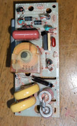
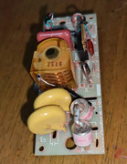
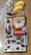
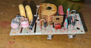
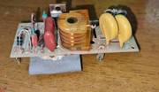
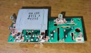
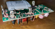
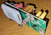
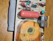
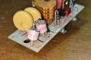
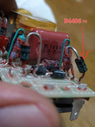
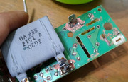
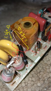
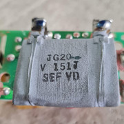
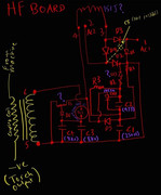
So I disassembled the faulty (I think) HF unit from my Thermal Arc 300GTSW (Single & 3 phase selectable) tig welder and now trying to figure out how the thing works. I have attached pictures of the circuit board and a crappy hand drawn circuit diagram. Arc is weak and wouldn't ignite on AC mode, DC welding is fine although the arc won't transfer at times. I would appreciate if anyone is kind enough to explain the workings of this board. There is no replacement part so my only option is to repair it and to do that, I have to first understand how it works. All I know is this board is supposed to generate high frequency high voltage as an ignition for the torch arc transfer.Also need help identifying that 151J part. What's it called, what it does and where can I find the datasheet for it? And why is diode D6 so long? It only has the number 79 on it, which I can't find on the internet. I assume T1 is the low to high voltage transformer? Why does it only have 3 terminals and why is it so small? All other info I searched on the internet on TIG HF starter circuit showed them to be pretty big and hefty like they weigh a pound or two. Is SSS a regular diode? It does appear to behave like a diode on my multimeter. Why is it bigger than the rest?On a site note, is there a reason these units are fully potted in silicone rubber? Is it necessary for its operation or is it just an attempt by the manufacturer to obfuscate things?Link to service manual can be found here:https://www.manualslib.com/manual/794240/Thermal-Arc-300gtsw-Pro-Wave.html
Last edited by newcomer9747; 5 Days Ago at 03:47 AM.
Reply:continued with pictures & diagrams
Reply:This may be of no help to you, but I have the same machine and had a problems similar to what you described. I took my machine to a local welding shop for repair figuring that the machine was probably toast. I didn't want to mess with the circuit boards thinking that I'd probably just make things worse. Turns out the guy working on the machine found that the welding cable under the dinse connector had worked loose and was causing the machine to misbehave. You could never tell it from looking and feeling the end of the cable. I felt really stupid and embarrassed over the whole thing, but I paid the diagnostic fee and was happy to get my machine back working.I'm sure that you've probably already checked the simple things like this before delving into the electronics, but it never hurts to double-check things that you would normally assume are OK.
Reply:The reason that T1, the HF output transformer only has only 3 connections is because the primary and secondary winnings share a connection, just like an automotive ignition coil. It is hard to trouble shoot a board level problem if there is no obviously defective or burned out part. You may end up guessing, so start with things that are cheap and easy to replace. It is also hard to check the function of diodes when they are in a circuit as you can get fooled by alternative paths. It may be necessary to isolate the part by unsoldering one lead. If I had to guess, I would guess the spark gaps (Siemens?).Tutorial on HF circuits:https://electronoobs.com/eng_circuitos_tut39.php
Reply:This is based a lot like an older design we had on Everlast. Those little canisters are "air tubes" (can't remember the proper name) that simulate the HF gap. They wear out. Replace those and you should be back up and going.Esab Migmaster 250Lincoln SA 200Lincoln Ranger 8Smith Oxy Fuel setupEverlast PowerPlasma 80Everlast Power iMIG 160Everlast Power iMIG 205 Everlast Power iMIG 140EEverlast PowerARC 300Everlast PowerARC 140STEverlast PowerTIG 255EXT
Reply:They are called gas discharge tube spark gaps and are typically used as surge protectors. I’m not sure why two are used in series. But older welding HF circuits have two spark gaps too. They regulate the HF voltage. If the voltage is too high,bad things can happen. High voltage will always find the easiest path to ground.
Reply:Potting is generally used to increase reliability of printed circuit boards in demanding enviroments. It also help insulate/isolate High Voltages from arcing across a PCB that might have some contamination like carbon dust , metal grinding dust, over even spider webs with some dampness. Having been involved in the manufacture, and repair of circuit board, and the repair, and maintenance of industrial manufacturing machinery, I know what your up against. Its getting harder to find some of the through hole electronic components in some of the less used values. Companies lose older documents for machinery, and circuit boards. You can wind up going down a rabbit hole and consume a lot of time. I try to set a time limit, and budget, some times a machine is worth it , or sometimes its not. I guess you already performed the HF tests from the manual to determine which board has the problem ?


Thats a pretty good manual to help trouble shoot, a full part list and schematic for the PCB may be available from the manufacturer. The PCB says SANREX on it , they may be the ones to call/Email. You might want to call York Elec in PA, they list a lot of boards from that manufacturer.http://www.yorkelectronics.com/html/about.html

Best of luck with your endeavor.

Airco 250 ac/dc Heliwelder Square waveMiller Synchrowave 180 sdMiller Econo Twin HFLincoln 210 MPDayton 225 ac/dcVictor torchesSnap-On YA-212Lotos Cut60DPrimeweld 225 ac/dcPrimeweld mig180Miller AEAD-200
Reply:Before they went out of business, I use to bring simple boards to the local TV repair shop.He could order any old components it seemed (cheap) and quickly swap them out on the board for me.(I don't really mess with tiny solder connections)Dave J.Beware of false knowledge; it is more dangerous than ignorance. ~George Bernard Shaw~ Syncro 350Invertec v250-sThermal Arc 161 and 300MM210DialarcTried being normal once, didn't take....I think it was a Tuesday.
Reply:D6 is long simply because it is a high voltage rectifier, and the others are not. Were it the same length as the others, it would likely arc over.
Reply:

Originally Posted by albrightree

Potting is generally used to increase reliability of printed circuit boards in demanding enviroments. It also help insulate/isolate High Voltages from arcing across a PCB that might have some contamination like carbon dust , metal grinding dust, over even spider webs with some dampness. Having been involved in the manufacture, and repair of circuit board, and the repair, and maintenance of industrial manufacturing machinery, I know what your up against. Its getting harder to find some of the through hole electronic components in some of the less used values. Companies lose older documents for machinery, and circuit boards. You can wind up going down a rabbit hole and consume a lot of time. I try to set a time limit, and budget, some times a machine is worth it , or sometimes its not. I guess you already performed the HF tests from the manual to determine which board has the problem ? |
|


 发表于 2022-9-16 15:52:17